

Bare-Rife Types
 |
 |
The Bare-Rife Method is by far and away the most popular for high quality, highest power systems preferred by serious experimenters and researchers today. Unfortunately, these systems are also typically the most expensive of all the types to construct and definitely require a certain level of experience and technique to build a stable and reliable system. As relatively high power modulated radio frequency (RF) is involved in the gas excitation to form the plasma, a good understanding of RF physics is particularly helpful.
Here we see a typical and practical component configuration for a solid Bare-Rife system. We will lightly discuss the components and their general use and purpose.
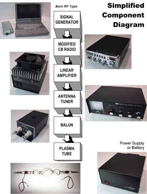 |
| Note: the power supply is not a component in the functional flow yet is an absolutely necessary component which supplies 12 volts dc power at high current to all the major components. |
SIGNAL GENERATOR – The basic input signal can be created by a wide variety of devices, from a laboratory grade function generator, to a simple computer generated audio waveform. This device generates the specific audio waveform at our target frequencies, which are to be placed, (input) on the RF carrier frequency. This happens much the same way as your favorite talk show hosts voice is placed on the radio station’s assigned carrier frequency. We are simply using more pure tones (and their harmonics) rather than complex voice patterns as the “active ingredient” for our use. Good laboratory grade frequency and function generators can be quite expensive and not typically easy for most folks to understand and use. They provide functions many folks will not ever need for Rife work. Computer generation and versatility has become a very versatile preference for many folks. In the “Frequency Generation” document I will discuss in detail many of the practical applications and considerations for good Rife experimentation.
MODIFIED CB RADIO – the CB band (Citizens Band) today contains a shared frequency allocation with the ISM band (Industrial-Scientific-Medical). The channel 14 we use is within that shared band making off-the-shelf general components readily available. However, CB radios were designed to carry voice communication, which does not need anywhere near the fidelity/bandwidth of music, nor does it need even the full spectrum of our hearing range. As a general rule, the frequencies used for Rife are manipulated within the audio ranges, but the characteristics of the square wave means that we are also dealing with harmonics (multiples) of those individual frequencies … and we ideally wish to pass at least some of them as well. Like the linear, modern CBs are not meant to be transmitting 100% of the time, typically only a few minutes at a time. Over heating and component breakdown, and thermal shut-off will often occur. Part of the modification process, generally uses “over-rated” components, and extensive cooling, to insure continued operation for extended periods of time.
LINEAR AMPLIFIER – This amplifier simply boosts the RF output as well as the contained modulation (audio) to a level sufficient to easily excite the Nobel gases within the plasma tube. As in the transmitter modifications, special consideration should be exhibited in selection and/or modification to allow the pass-through (rather than blocking) of the extended modulation bandwidth being issued by the modified CB. Additionally, most modern day amplifiers are made for (at best) a 50% duty cycle, appx 5 minutes on, then 5 minutes off, giving it a period to cool down. Because of the power ratings of the components, this is a far more critical issue of concern and consideration than in the CB.
ANTENNA TUNER – The tuner actually matches the cable electronically so that the throughput of the signal is least restricted and flows with minimal effort. Restriction causes heat build up on not only the cabling, but more seriously the components themselves causing premature failure. It is extremely important to see that SWR (Standing Wave Ratio) is kept at an absolute minimum. Failure to do so, WILL result in component weakening and permanent damage.
BALUN - the balun is actually a relatively simple device used to match an unbalanced line output, (typically a 50 ohm coax), to a balanced line, (typically 2 identical pieces of wire), connected to the antenna. The baluns we typically have used to date were generally manufactured for amateur radio communication. The ratings on most off-the-shelf baluns do NOT correspond to our typical power ratings. For instance, even running 100watts of forward power being delivered efficiently into the plasma, a balun rated at 300watts will quickly fail, (seconds to minutes). Even a balun rated at 1500-2000 watts often can get quite warm in a Bare-Rife environment. Intense heat can cause a fracturing of the structure of the balun core which can go unnoticed. It is believed that the “Rife-effect” is not passed when the core is in either the overheated state or ever again after the core is fractured. Unfortunately, this fracturing is not necessarily visible nor does it always reflect in the performance of the visible indications and excitation of the plasma tube.
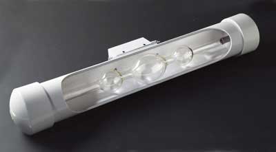
PLASMA TUBE – Of course this is the place that is characteristically the most visible of the individual functional components and of that characteristic violet/mauve color what we strive for. However, the real “magic” probably has little to do with the visual components. Tube and gas type selection can and should be a very personal decision. The document entitled “Tube Types & Considerations” will discuss and pictorially illustrate many of the features, and issues.
POWER SUPPLY - Universal 12 volt DC power
is supplied to many of the individual components. A quality,
high current, power source (which might be battery/s) is absolutely
required for stable operation.
Of course the previous diagram is over simplified but does
represent actual components used in a RF Rife system. Importance
should be places on using quality components, appropriate
wiring, connectors, and routing using good engineering practices
for high current and RF installations. Failure to do so can
result in inferior to disastrous results.
It is beyond the scope, and NOT the intent of this document
to describe in detail the construction of a Bare-Rife Device
… although we highly recommend the experience. Elsewhere
in this book we will be showing numerous construction details,
photos, hints and recommendations for Bare-Rife construction.
If you are considering building a Bare Rife system, we cannot
place enough emphasis on recommending the purchase of Jim
Bare’s book, “Resonant Frequency
Therapy: Building the Rife Beam Ray Device”.
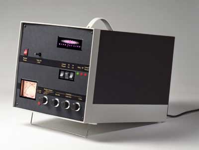
| Transportable Bare-Rife System |
The “Transportable Rife” is shown here in its carrying case. It is not necessary to remove the unit for operation as the layout and design makes provisions for adequate cooling and access to necessary controls. Wrapped tube can be easily detached and stored in an appropriate heavy duty PVC tubing with appropriate padding.
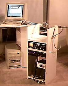
| Transportable & Laptop |
 |
| Stand-Alone with Single Bubble Tube |